


Advanced System Architecture
Proprietary framework design optimized for intelligent system integration.
Nvisco, your excellence partner. One team takes your idea to a product-ready design.


“I have an idea, and I want you to build…”
Proprietary framework design optimized for intelligent system integration.
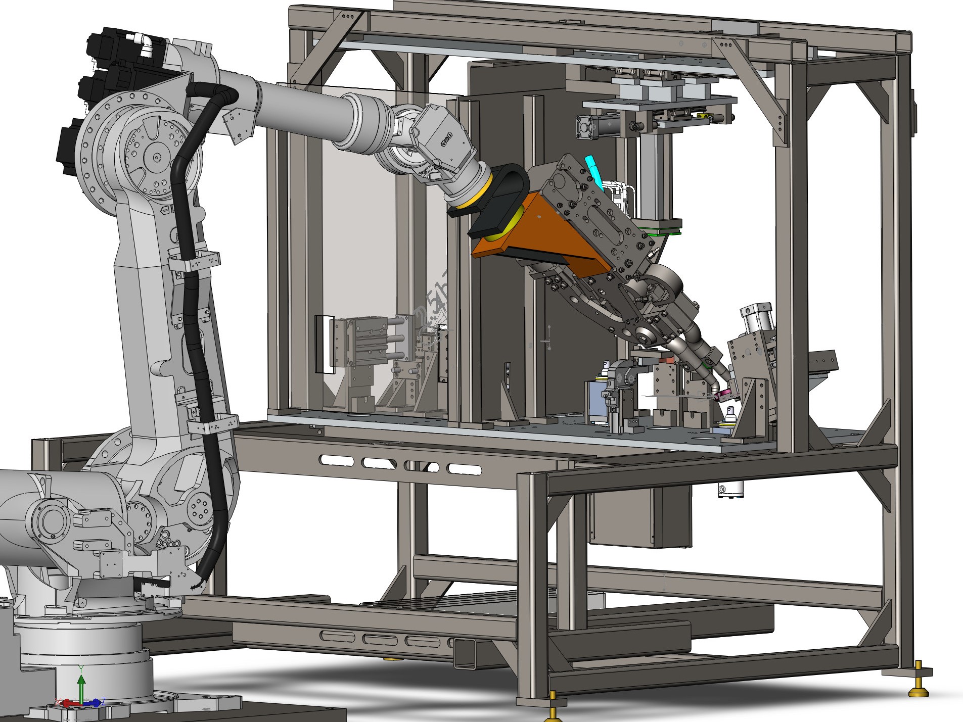
Precision 3D mechanical models and layered architectures.
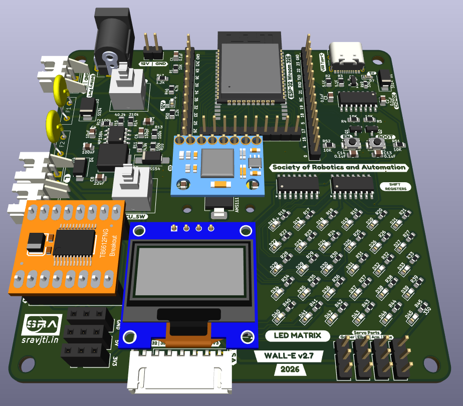
Merging mechanical hardware, electronics, and logic firmware.
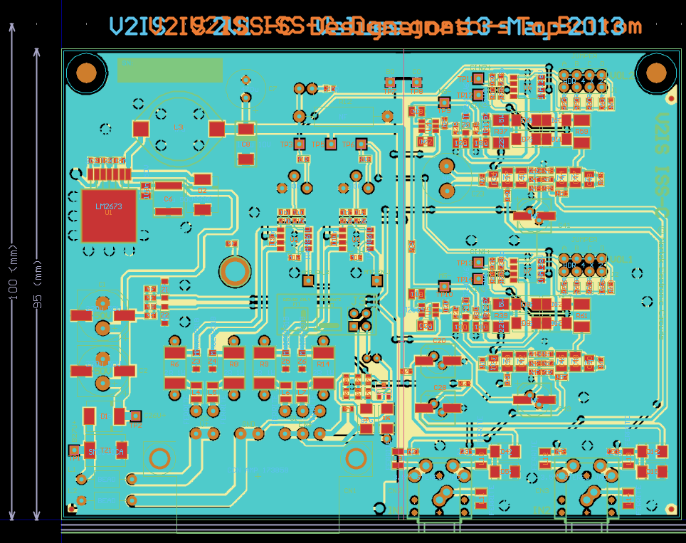
Optimized architectures for high-speed computation.
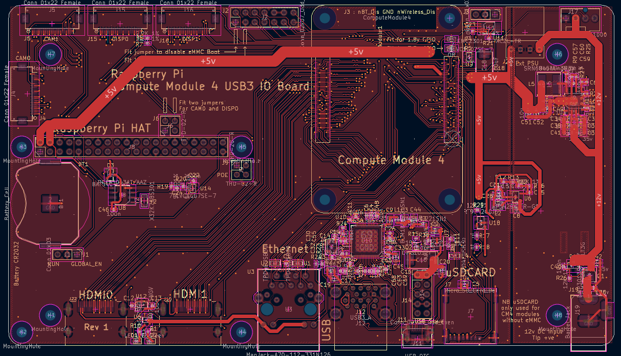
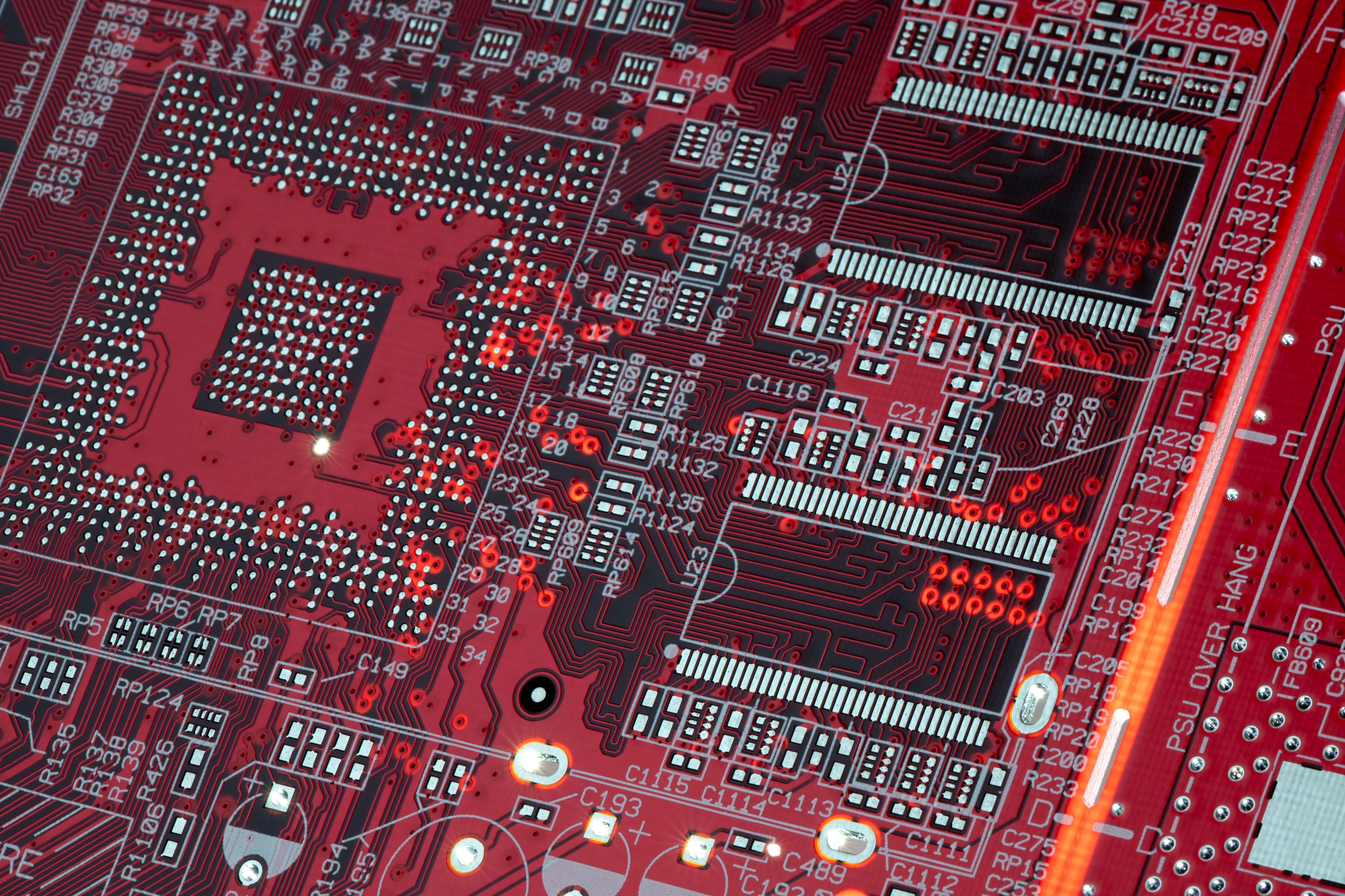
Advanced high-density PCB layouts engineered for maximum performance.
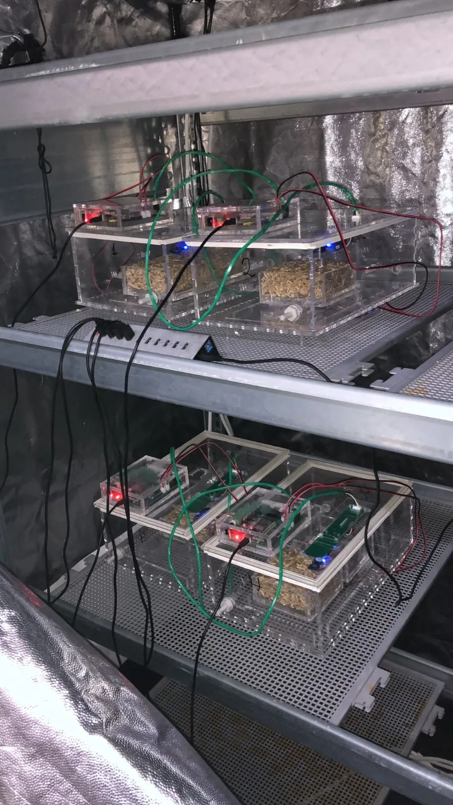
Automated systems built for continuous precision in demanding environments.
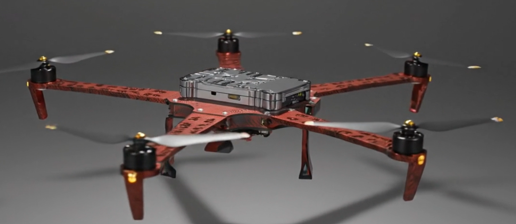
Precision 3D CAD modeling for industrial and consumer cases.
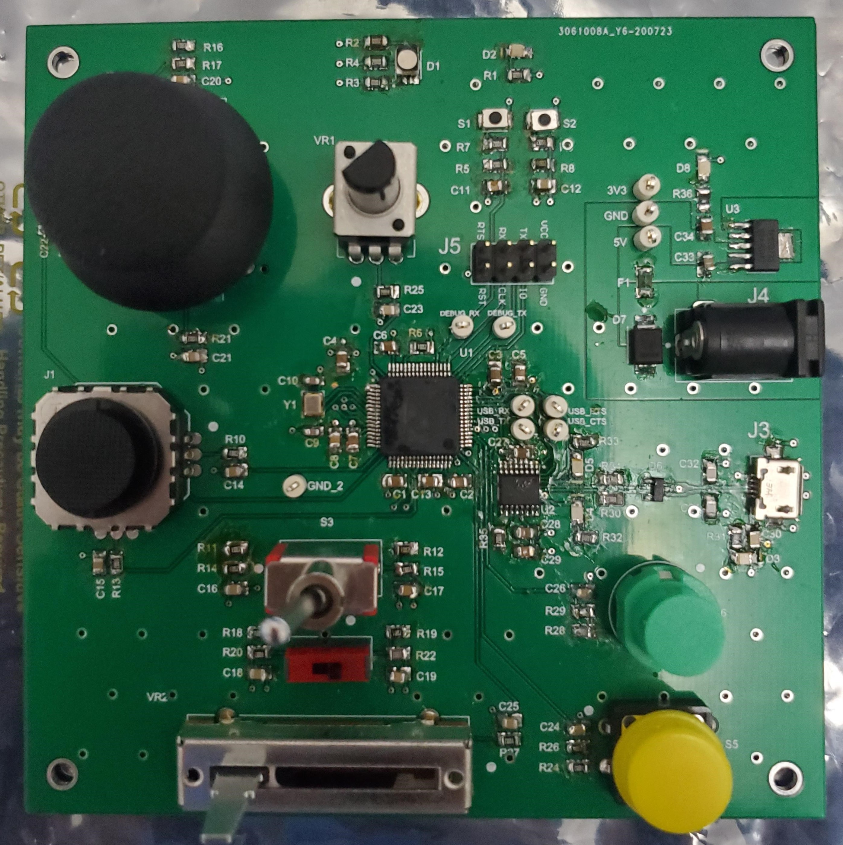
Custom RF layouts and antenna tuning for robust wireless transmission.
The IPC standards our designs follow, from board architecture to the files a factory builds from. Open any standard to see what it covers, its current edition and how we use it.
These standards govern complex, tightly packed electronics, so signals and structures stay reliable.
The IPC-2220 series is the design backbone for printed boards. IPC-2221 sets the generic rules for every board, and sectional standards such as IPC-2222 (rigid boards) and IPC-2226 (HDI boards) add the rules for a specific technology. They are used together: the generic standard first, then the sectional standard that matches the board.
How we use it. Every Nvisco layout starts from this series. We choose the sectional standard that matches your board before the first trace is drawn.
The foundation document of the series. It covers material and copper foil selection, conductor spacing, hole and land sizes, electrical clearance (including creepage and dielectric withstanding voltage), impedance tolerances, press-fit pins and back-drilling. Revision C supersedes IPC-2221B.
How we use it. It is our baseline for stack-up and material choice, conductor spacing and high-voltage clearance. For mains-connected products we also follow the end-product safety standard, because IPC-2221 is a board design standard, not a safety standard.
Adds the rules that are specific to rigid boards built from organic materials such as FR-4: construction types, materials, mechanical and hole requirements, lands and circuit features. It builds on IPC-2221.
How we use it. Applied to our rigid multilayer designs, from simple two-layer boards to dense multilayer stack-ups.
Covers high-density interconnect boards: microvias, blind and buried vias, via-in-pad, fine-pitch BGA breakout and the build-ups that make them manufacturable. It is used together with IPC-2221.
How we use it. Applied to complex, space-constrained designs, including our high-density layouts of up to 22 layers.
These standards keep boards from mistiming, overheating or failing during automated assembly.
Guidance for controlling impedance and signal timing on fast signals: trace geometry, dielectric choice, and how the stack-up affects impedance.
How we use it. We set impedance targets and the stack-up before routing, then do length matching and tuning on fast buses so signals arrive together.
Based on measured data, it shows how much current a trace can carry for a given temperature rise, taking copper weight, trace width, planes and board thickness into account. It replaces the older charts that were part of IPC-2221.
How we use it. We size power and motor traces, copper weights and thermal paths with it, so heavy power lines run safely without overheating.
Defines how to design land patterns (footprints) for surface-mount parts, with a naming convention and three density levels: Level A (most), B (nominal) and C (least) land protrusion. IPC-7352 (2023) is the newer companion guideline for land pattern design.
How we use it. Every custom footprint is built to the IPC density level that suits the product, for reliable solder fillets and clean automated assembly.
These standards make sure the files we hand over can be built by a factory without errors or endless revisions.
Defines what a finished rigid board must meet, in three classes: Class 1 general electronics, Class 2 dedicated-service electronics and Class 3 high-performance or harsh-environment electronics. It sets limits for plating, annular rings, hole quality and more.
How we use it. We design annular rings, drill sizes and tolerances so your fabricator can meet Class 2 or Class 3, whichever your product needs.
The illustrated inspection guide for bare boards. It shows what is acceptable, and what is not, for each class, and is the visual companion to IPC-6012.
How we use it. We design features so a bare board passes inspection at your chosen class, and we state that class in the fabrication notes.
The acceptance guide for assembled boards: solder joints, component placement, cleanliness and coating. It assumes the bare board already meets IPC-A-600.
How we use it. We lay out and document assemblies, with correct footprints, polarity marks and test points, so acceptance at Class 2 or Class 3 is straightforward for the assembler.
An open, single-file data format that carries the stack-up, drill data, netlist, bill of materials and fabrication notes together, replacing separate Gerber and drill files that have to be matched by hand.
How we use it. We supply IPC-2581 where your fabricator accepts it, together with conventional manufacturing files, so nothing is ambiguous.
Standards are published by IPC (Global Electronics Association). We design to their published requirements; this is not an IPC certification or endorsement. Editions shown are the current ones listed by IPC and its distributors in October 2026, so please confirm the edition named in your project documents.
Free consultation. We can sign an NDA before you share anything.